- [行业新闻]Microchip晶振DSC613系列3路输出低功耗MEMS时钟振荡器DSC613RI3A-010UT2022年08月04日 08:58
DSC613系列器件是业界最小的MEMS时钟发生器,可替代板上最多三个晶体和振荡器,从而将时序元件板空间减少多达 80%。时钟发生器通过集成低功率和高稳定性的微机电系统 (MEMS)谐振器,无需外部晶体。该系列包括两个低功耗分数 PLL,可提供领先的频率灵活性和稳健的抖动性能。客户可以配置输出频率、控制引脚功能、封装尺寸、PPM 精度和温度范围。根据自定义电路板负载条件,最多可提供三种输出驱动强度。扩频时钟也可用于降低 EMI。DSC613是一款高度可配置的器件,出厂时已编程以满足客户的需求
Microchip晶振DSC613系列3路输出低功耗MEMS时钟振荡器DSC613RI3A-010UT
- 阅读(758)
- [行业新闻]亚陶晶振KX201系列在广泛的工作条件下实现了卓越的稳定性,KX201VIS032.768000时钟振荡器2022年08月01日 11:48
亚陶晶振KX201系列实时时钟振荡器在广泛的工作条件下实现了卓越的稳定性。它利用Pericom专有技术实现低于30μA的超低电流。输出时钟信号与LVCMOS/LVTTL逻辑电平兼容。该器件采用卷带包装,采用2.0x1.6mm表面贴装陶瓷封装。
特征:
AT Cut 32.768kHz XO
CMOS兼容逻辑电平
超低有功电流(< 30μA)
非常严格的温度稳定性
专为标准回流和清洗技术而设计
无铅且符合 RoHS/Green 标准
应用:需要低电流和高度稳定性的实时时钟振荡器亚陶晶振KX201系列在广泛的工作条件下实现了卓越的稳定性,KX201VIS032.768000时钟振荡器
- 阅读(688)
- [行业新闻]大真空旗下两款基站用Oscillator性能详细剖析介绍2021年01月15日 13:46
大真空旗下两款基站用Oscillator性能详细剖析介绍.
DC7050AS和DSA/DSB535SGA是大真空旗下的可用于通信基站的石英晶振产品,其中DC7050AS是一款恒温晶振, DSA/DSB535SGA中DSA系列是压控温补晶振,DSB系列是温补晶振系列;对于通信基站来说,工作环境的复杂性决定了它所使用的晶体频控元件必须是能够承受复杂环境所带来的的影响.
- 阅读(186)
- [行业新闻]日本毕业典礼能顺利进行是机器人振荡器的功劳2020年04月13日 17:21
- Newme机器人减少了人员的接触,让大学毕业生顺利毕业,是研发部又一大贡献.在大家眼中机器人可以代替普工的劳动生产,是减少服务员的招聘,谁又能想到可以用在毕业典礼上.校方和机器人一起见证毕业时代,是多么值得开心的时刻,看它的整体照片是有点怪怪的,但总的来说还是对社会的一大贡献.这一贡献少不了研发公司的投入,技术人员的精益求精,振荡器的应用.
- 阅读(135)
- [行业新闻]iPhone XR遭到举报影响晶振的整体发展2020年04月10日 17:06
- iPhone XR通讯,接收方面出了问题,整体的口碑大家可以想象.之前受到多个国家追捧的苹果手机,现在显得有点黯淡,难道就要就此落寞,在这打一个疑问号.苹果手机在这两年销量被后来者居上长为常态,很明显苹果往日的辉煌不再.那苹果销量下降,内部石英晶体振荡器的使用量也不再需要那么多.往日对苹果公司大量供应元器件的厂家盈利减少,在晶振的投资金额也是有限,这样对于晶振的发展是很不利的.
- 阅读(152)
- [行业新闻]石英晶体负载电容还有频率吗?2019年11月07日 14:54
石英晶体负载电容还有频率吗?这句话听起来又矛盾又好奇,为什么负载电容里面还会有频率出现.我们所知道的不都是石英晶振产品内部有标准频率参数,负载电容值,频率偏差以及工作温度等相关参数,但又是为什么石英晶体负载电容还会有频率呢?那么以下,请跟随着我们来去了解探讨一下有关于<石英晶体负载电容还有频率吗?>的疑问!
当订购用于工作在频率f下的振荡器的晶体时,例如32.768 kHz或20 MHz,通常仅指定工作频率是不够的。尽管晶体将以接近其串联谐振频率的频率振荡,但实际的振荡频率通常与该频率稍有不同(在“并联谐振电路”中会稍高一些)1。
因此,假设您有一个晶体振荡器电路,并且想要购买晶体,以使放置在该电路中时的振荡频率为f。您需要告诉晶振厂家完成什么?您是否需要发送振荡器设计的示意图以及其设计的所有相关细节,例如选择与布局相关的电容器,电阻器,有源元件和杂散?幸运的是,答案是否定的。除了频率f之外,仅需一个数字,即负载电容CL。
2.什么是CL?
假设您的晶体振荡器以所需的频率f运行。在该频率下,晶体具有复阻抗Z,并且对于工作频率而言,这是晶体唯一重要的特性。因此,为了使振荡器在频率f下工作,您需要在频率f下具有阻抗Z的晶体。因此,最糟糕的是,您只需指定一个复数Z = R + jX。实际上,它甚至比这更简单。
尽管原则上应该在频率f处指定晶体电阻R,但通常R中的晶体间差异以及振荡器对此变化的敏感性足够低,因此无需指定R。这并不是说抗结晶性没有影响;是的。我们将在第4节中进一步讨论。
因此,剩下一个值来指定:f处的晶体电抗X。因此,可以指定一种在20 MHz时电抗为400的晶体。取而代之的是,通常通过指定电容CL并等于

在这里我们设定了ω=2πf。 在物理上,在该频率下,晶振和电容CL的串联组合的阻抗具有零相位(等效地,具有零电抗或纯电阻)。 参见图1。

其中第二步遵循公式(1),电容C的电抗为-1 /(ωC)。
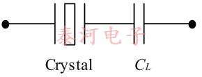
图1-该串联组合在晶振具有负载电容CL的频率下具有零相阻抗
因此,确保适当的振荡频率的任务是提供在指定频率下具有所需电抗的组件(在这种情况下为晶体),这由等式(1)2用电容CL表示。例如,我们不是指定晶体在20 MHz时具有400 frequency的电抗,而是指定在20 MHz处具有20 pF的负载电容的晶体,或更通常地,我们指定在20 pF的负载电容下的晶体频率为20 MHz。
在“并联谐振电路”中,CL为正,通常在5 pF至40 pF之间。在这种情况下,晶体在晶体的串联和并联谐振频率(分别为Fs和Fp)之间的狭窄频带内工作。
注释:1订购晶体进行串联谐振操作时,不要指定CL的值,而应声明频率f指的是串联谐振频率Fs。
2这并不是说频率确定的所有方面都与此唯一数字相关。例如,晶体和振荡器的其他方面决定了是否选择了正确的振荡模式以及系统的频率稳定性(短期和长期)。
虽然真正的“串联谐振电路”没有与之相关的负载电容[或方程式(1)可能是无穷大],但大多数“串联谐振电路”实际上实际上是在串联谐振频率之外工作的,因此确实有一个有限负载电容(可以为正或负)。但是,如果此偏移很小,并且不需要指定负载电容,则可以忽略该偏移,也可以通过在指定频率f中稍有偏移来处理它。
正如我们将在第4节中看到的那样,振荡器和晶体都确定CL。但是,该晶体的作用很弱,因为在零电阻的极限内,该晶体在确定CL时根本不起作用。在这种限制情况下,将CL称为振荡器负载电容是有意义的,因为它完全由振荡器决定。但是,到了在订购晶体的时间上,可以指定在负载电容CL处具有频率f的晶体,即这是晶体频率的条件。因此,将CL称为晶体负载电容是合理的。出于争论的目的,我们简单地避免了这个问题,并使用术语负载电容。
3.在CL上定义FL
现在,对于在给定的负载电容下具有给定频率的晶体,我们用方程式(1)作为定义关系。
定义:当晶体在频率FL处的电抗X由公式(1)给出时,晶体在负载电容CL处具有频率FL,其中ω=2πFL。
回想一下,在给定模式下,晶体的电抗从负值增加,在串联谐振时从零增加到在并联谐振附近的大正值,在此它迅速减小到大负值,然后又增加到零。 (参见参考文献[1]。)通过排除并联谐振周围的区域,我们为每个电抗值提供了一个频率。这样,我们可以关联给定CL值的频率FL。因此,CL的正值对应于串联谐振和并联谐振之间的频率。 CL的大负值对应于低于串联谐振的频率,而较小的负值对应于高于并联谐振的频率。 (请参见下面的公式(3)。)
3.1。 晶体频率方程
那么,振荡频率在多大程度上取决于负载电容CL? 我们可以通过确定晶体频率FL如何取决于晶体负载电容CL来回答这个问题。 可以证明这一点非常近似
其中C 1和C 0分别是晶体的动电容和静电容。 (有关该关系的推导和讨论,请参见参考文献[1]。)为便于说明,我们将公式(3)称为晶体频率公式。
这表明晶体振荡器的工作频率与其负载电容的相关性以及对晶体本身的相关性。 特别地,当将负载电容从CL1更改为CL2时,分数频率变化可以通过以下方式很好地近似:

3.2。 修剪灵敏度
公式(3)给出了工作频率FL对负载电容CL的依赖性。 频率随CL的负变化率称为调整灵敏度TS。 使用公式(3),这大约是

由此可见,在较低的CL值下,晶体对CL的给定变化更敏感。
4.但是什么决定CL?
考虑一个简单的皮尔斯振荡器,它由一个晶体,一个放大器以及栅极和漏极电容器组成,如图2所示。

试图计算皮尔斯振荡器电路的负载电容时,必须考虑至少三个杂散电容。
1.从放大器的输入到地面的附加电容。其来源可能是放大器本身,并且将电容跟踪到地。由于此电容与C G并联,因此我们可以简单地将其吸收到C G的定义中。 (CG是电容器对地的电容加上放大器此侧对地的任何附加电容。)
2.从放大器的输出到地面的附加电容。其来源可能是放大器本身,并且将电容跟踪到地。由于此电容与C D并联,因此我们可以简单地将其吸收到C D的定义中。 (即CD是电容器接地电容,再加上放大器此侧的任何其他接地电容。)
3.杂散电容C s使晶体分流,如图2所示。
如上所述重新定义C G和C D,然后得出[2]振荡的条件之一是

Where

是晶体和电容C s的并联组合的阻抗,而R o是放大器的输出电阻。
可以看出,晶振电阻R是负载电容CL的函数,近似为:(假设CL不太小)

其中R 1是晶体[1]的运动阻力。
然后得出结论(提供的CL – C s不太小)

以及

根据这些结果,式(6)给出了CL的以下方程式

其中R′由等式(9)近似。请注意,CL的方程实际上比起初看起来要复杂一些,因为R'取决于CL。
可以看出,CL随R 1的增加而减小,因此通过公式(3),工作频率随晶体电阻而增加。因此,负载电容确实与晶体本身有关。但是,正如我们前面提到的,晶体电阻的变化以及对这种变化的灵敏度通常足够低,因此可以忽略不计。 (在这种情况下,晶体电阻的标称值用于计算CL。)
但是,有时抗拒效果不容忽视。调谐两个晶体,以使它们在给定的负载电容CL下具有完全相同的频率,如果它们的电阻不同,则它们可以在同一振荡器中以不同的频率振荡。这种微小的差异导致所观察到的系统频率变化增加,高于晶体频率校准误差和板对板组件变化所引起的变化。
注意,在晶体电阻为零的情况下(或与放大器的输出电阻R o相比,至少可忽略不计),公式(11)给出

因此,在这种情况下,负载电容是将晶体分流的杂散电容加上晶体每一侧的两个电容与地之间的串联电容。
5,测量CL
虽然原则上可以从电路设计中计算出CL,但是一种更简单的方法是简单地测量CL。这也更加可靠,因为它不依赖于振荡器电路模型,考虑了与布局相关的杂散(可能难以估计),并且考虑了晶体电阻的影响。这是两种测量CL的方法。
5.1方法1
该方法需要阻抗分析仪,但不需要了解晶体参数,并且与晶体模型无关。
1.获得与将要订购的晶体相似的晶体,即具有相似的频率和电阻。
2.将此晶体放置在振荡器中,并测量操作FL的频率。将晶振放入电路中时,请注意不要损坏它或做任何会引起不适当频率偏移的事情。 (如果焊接到位,请使其冷却至室温。)避免焊接的好方法是简单地使用例如铅笔的橡皮擦末端将晶体压在板的焊盘上,并观察振荡频率。只要注意晶体与电路板完全接触即可。该系统仍然可以以较高的频率振荡,而晶体不会与电路板完全接触。
3.使用阻抗分析仪,以步骤2中确定的频率FL测量晶体的电抗X。
4.使用等式(1)以及在FL处的FL(ω=2πFL)和X的测量值来计算CL。
5.2方法2
此方法取决于四参数晶体模型,并且需要了解这些参数(通过您自己的测量或晶体制造商提供的知识)。
1.获得与将要订购的晶体相似的晶体,即具有相似的频率和电阻。
2.表征该晶体。特别要测量其串联频率F s,运动电容C 1和静态电容C 0。
3.将此晶体放在振荡器中,并测量操作FL的频率(如方法1,步骤2所示)。
4.使用公式(3)和FL,F s,C 1和C 0的测量值计算CL。
建议采用至少3个晶体进行这两种方法。正确完成后,该技术通常得出的CL值约为0.1 pF。通过对多个电路板重复该过程以估计CL的电路板间差异,可以找到对最终结果的进一步信心。
注意,在上面,FL不必精确地是期望的振荡频率f。也就是说,CL的计算值不是振荡频率的强函数,因为通常仅晶体是强烈依赖于频率的。如果由于某种原因,振荡器确实具有很强的频率相关性,那么使用该程序将非常困难。
6.我真的需要为CL指定值吗?
至少有三种情况不需要CL的规范:
1.您打算以晶体的串联谐振频率进行操作。
2.您可以容忍频率中的较大误差(大约0.1%或更高)。
3.电路的负载电容足够接近标准值(请参见晶振数据表),以允许频率差。可以使用公式(4)计算该差异。
如果您的应用不满足上述三个条件之一,则应强烈考虑估算振荡器的负载电容,并在指定晶体时使用该值。
- 阅读(216)
- [行业新闻]Resonators的各项参数及性能2019年11月05日 14:39
石英晶体谐振器在电子学中的重要性在于其极高的Q值、相对较小的尺寸和优异的温度稳定性。
石英晶体谐振器利用石英的压电特性直接压电效应是指机械应力作用下某些材料产生的电极化效应。逆效应是指同一材料在电场作用下产生的变形。
在石英晶体谐振器中,在两个电极之间放置一薄片石英,其相对于晶体轴以适当的方向切割。施加在这些电极上的交流电压会使石英同时振动。伴随而来的极化变化构成了通过谐振器的电位移电流。
当外加电压的频率接近石英薄片的机械共振频率之一时,振动的振幅变得很大。伴随的位移电流也会增大,因此器件的有效阻抗会减小。在石英晶体谐振器作为晶体振荡器的频率控制元件的应用中,阻抗随共振附近频率的变化而迅速变化是关键因素。
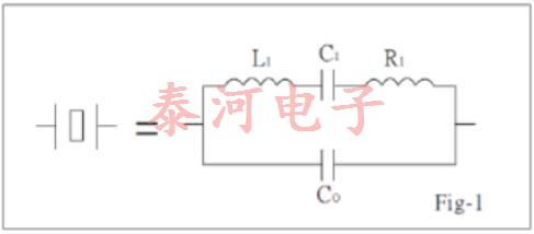
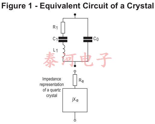
在电气方面,石英晶体可以用图1中的等效电路表示,其中串联组合r1、l1和c1表示压电效应对阻抗的贡献,c0表示电极之间的并联电容以及任何杂散保持器电容。电感l1是石英质量的函数,而电容c1与其刚度相关。电阻r1是石英和安装装置损耗的结果。等效电路的参数测量精度可达1%左右。
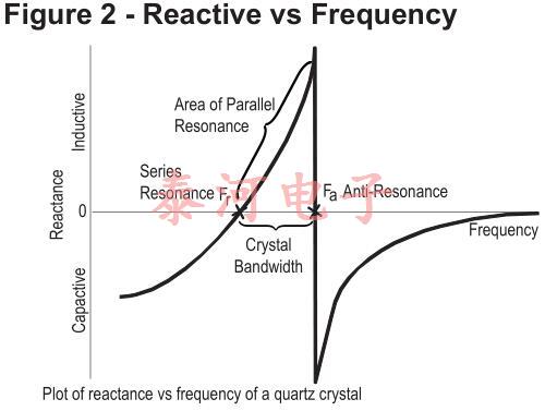
等效电路的电抗频率图如图2所示。晶振性能的相关公式有很多,其中第一个是fs。这是晶体串联共振的频率,由下式给出:

其中fs以赫兹表示,l1以亨利表示,c1以法拉表示。
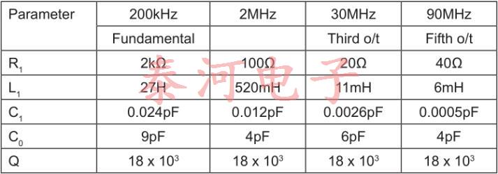
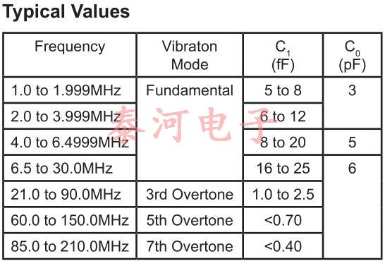
典型晶体参数值
校准公差
校准公差是晶体在特定温度、基准温度(通常为25°C)下频率的最大允许偏差。
频率稳定性
晶振不稳定有多种原因。温度变化和质量的物理变化导致了我们称之为老化的长期漂移,这可能是我们最关心的问题。
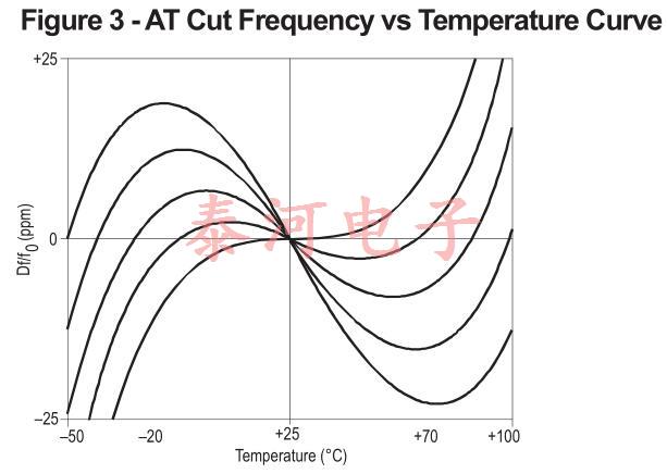
通过适当选择晶振切割和(对于严格的公差要求)在晶振电路中包括与温度相关的电抗,或在小烤箱中保持恒定温度,可将温度变化的影响降至最低。at-cut晶体是当今应用最广泛的晶振,因为它们的频率-温度曲线家族很容易以低成本为所有应用(除了最苛刻的应用)提供良好的性能。
未补偿的AT切割晶体可以在-10°C到60°C的范围内规定公差为±5ppm,更宽的温度范围需要更大的公差,如图3所示,显示了AT切割频率温度曲线的典型系列这些曲线可以用三次方程表示,并且强烈依赖于石英坯料的切割角度零温度系数的点称为上下拐点通过选择切割角度,可以将一个转折点放置在需要的位置;然后固定另一个转折点,因为这两个转折点在20°~30°C范围内的某个点上是对称的。转弯点之间的坡度随着它们一起移动而变小。设计用于烘箱的晶体被切割,以便上转折点与烘箱工作温度一致。
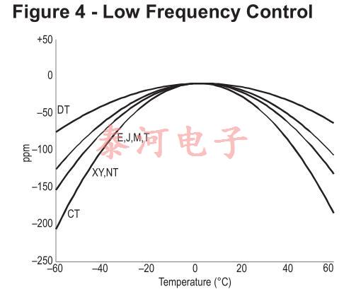
图4显示了几个低频切割的频率-温度曲线。J-cut在10kHz以下使用,而XY-cut可以在3kHz到85kHz之间使用。可在10KHz范围内使用NT切割。dt-cut适用于100khz至800khz左右,ct-cut适用于300khz至900khz。
负载电容
晶振可以由其制造商在fr处进行校准,在fr处它们看起来是电阻的(或非常接近fr的fs),或者在与电容性负载共振时,它们当然必须是电感的。后一种情况称为负载共振,通常用符号fl表示;更具体地说,符号f30,例如,表示晶体与30pF电容性负载共振的频率。

晶体电抗曲线上需要校准的点由电路结构决定一般来说,振荡器中的非反相保持放大器需要在fr处校准,而反相放大器需要在“负载电容”cl的某个值处校准。后一种配置依赖于电感晶体以及与之共振的负载电容,提供180度的相位偏移。
该规则最常见的例外是,当小电容器(例如变容二极管)与非反相放大器电路中的晶体串联以提供一定程度的频率调整时。在这种情况下,必须用电容的平均值校准晶体的共振。
可拉性
晶体的可拉性是在给定的负载电容变化下测量其频率变化的一种方法。这通常表示为串联谐振频率(fr)和负载谐振频率(fL)之间的差异该偏移量可使用分数负载谐振频率偏移量(dl)以百万分之几计算,即给定值cl时,从fr到fl的实际频率变化。

其中C1,C0和CL均以相同单位表示。图5显示了频率变化相对于负载电容变化的影响的典型曲线。

另外,通常将晶体的可拉性表示为修整灵敏度,单位为ppm / pF负载电容变化。 通过ppm / pF给出:

其中C1,C0和CL以pF为单位,并且在图6中以图形方式显示了(C0 + CL)的各种值。
- 阅读(421)
- [行业新闻]Analyze the aging of quartz crystal2019年10月31日 11:50
The 'ageing' of a quartz crystal results in a small change of frequency over time and this effect may have to be taken into account by the customer when designing their circuit depending upon the overall specification that needs to be achieved. There are two main causes of ageing in quartz crystals, one due to mass-transfer and the other due to stress.
Mass-Transfer
Any unwanted contamination inside the device package can transfer material to or from the SMD CRYSTALcausing a change in the mass of the quartz blank which will alter the frequency of the device. For example, the conductive epoxy used to mount the quartz blank can produce 'out-gassing' which can create oxidising material within the otherwise inert atmosphere inside the sealed crystal package and so this production process must be well controlled. Ideally the manufacturing method is as clean as possible to negate any effects and give good ageing results.
Stress
This can occur within various components of the crystal from the processing of the quartz blank, the curing of the epoxy mounting adhesive, the crystal mounting structure and the type of metal electrode material used in the device.Heating and cooling also causes stress due to different expansion coefficients. Stress in the system usually changes over time as the system relaxes and this can cause a change in frequency.
Ageing in practice
When looking at example ageing test results of crystals,it can be seen that the change in frequency is generally greatest in the 1st year and decays away with time. It must be noted however that for example if a device is specified at ±5ppm max per year; it does not follow that the ageing after 5 yrs will be ±5ppm x 5yrs, i.e. ±25ppm. In practice,the example ±5ppm ageing device may be only ±1ppm to ±2ppm in the 1st year of operation and then reduces over subsequent years. It is common to use a general 'guide-rule' for crystal ageing of ±10ppm max over 10 years although in reality it is usually much less than this. It is impossible to predict the exact ageing of a device as even parts made at the same time and from the same batch of quartz will exhibit slightly different ageing characteristics.The production process must be consistent from part to part, from the manufacture of the quartz blank, the electrode size and its placement, to the epoxy used to mount the quartz and its curing thermal profile, all have a slight affect on frequency. Devices can age negatively or positively depending upon the internal causes although parts from one batch tend to follow similar results. Generally the ageing effect is negative in over 90% of parts manufactured.
Accelerated ageing
It is common industry practice to use an accelerated ageing process to predict long term frequency movement by soaking devices at elevated temperatures and measuring frequency movement at relevant intervals. It is normal to test crystals using a passive test (i.e. non-powered). The general rule used is that soaking a crystal at +85℃ for 30 days is equivalent to 1 year of ageing at normal room temperature. If this test is extended for enough time then the recorded data can be plotted graphically to enable via extrapolation, the prediction of future long term ageing.
Frequency adjustment
Note that the ageing of quartz effectively changes the frequency tolerance of the crystal and does not directly influence the stability of the quartz over temperature to any great degree as this parameter is dictated by the 'cut-angle' of the quartz used. If using quartz oscillators that have a voltage-control function such as VCXOs, TCXOs or OCXOs, the output frequency can be adjusted back to its nominally specified value.
Design
The engineer designing a circuit using either a crystal or oscillator will generally know what overall stability figure their equipment must meet over a particular time period.
As the tolerance and/or stability of a device decreases then the more important ageing becomes. For example using a TCXO at ±1ppm stability over temperature will require ageing to be kept to relatively small values. However, if the total frequency movement allowance of a design is for example ±200ppm and a device with a rating of ±100ppm is used then a small amount of ageing can effectively be ignored.
- 阅读(190)
- [行业新闻]Crystal parameters description2019年10月29日 10:37
About Crystal parameters description,Crystal Project Name
AT Cut Crystals
For precise frequency control in radio and line communication systems, quartz crystal resonators have proved indispensable. The material properties of crystalline quartz are such that quartz resonators display stableness and Q factors that cannot be matched by other types of resonator over the frequency range from 1 MHz to 200 MHz.
Equivalent Circuit
Fig-1 shows the conventionally accepted equivalent circuit of a crystal resonator at a frequency near its main mode of vibration. The inductance LI reiperesents the vibrating mass, the series capacitance CL the compliance of the quartz element and the resistance Rl the internal frication of the element, mechanical losses in the mounting system and acoustical losses to the surrounding environment.
The shunt capacitance Co is made up of the static capacitance between the electrodes, togettier with stray capacitances of the mounting system.
There are two zero-phase frequencies associated with this simple circuit, one is at series resonance fs, another at antiresonance fa. When used in an oscillator, crystal units will operate at any frequency within the broken lines of Fig-2 as determined by the phase of the maintaining circuit.
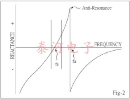
By changing of this reactive condition, the crystal frequency may be trimmed in a limited extent. The degree to which this frequency may be varied (frequency pulling) is inversely proportional to the capacitance ratio r(C〇 /Ci).
Load Capacitance
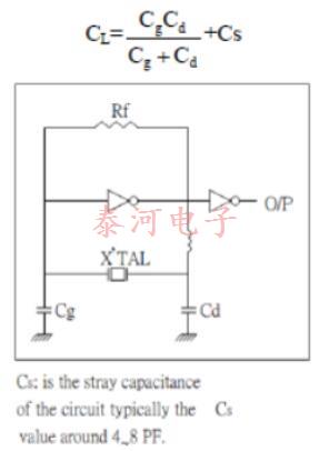
Many practical oscillator circuits make use of a load capacitor CL in series or parallel with the crystal, either in order to provide a means for final frequency adjustment, or perhaps for modulation or temperature compensation purposes. For the crystal load capacitance. We looking into the circuit through the two crystal terminals, the load capacitance need to specified when the crystal is paralleled mode, crystal load capacitance is calculated as below:
Frequency Pulling
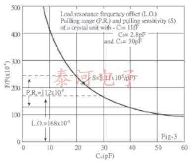
In many applications a variable capacitor (trimmer) is used as the load reactive element to adjust the frequency. The fractional frequency range available between specified values of this load reactive element is called the pulling range (PR.) and it can be calculated by using the following formula:

Sensitivity
A useful parameter to the design engineer is the pulling sensitivity (S) at a specified value of load capacitance. It is defined as the incremental fractional frequency change for an incremental change in load capacitance. It is normally expressed in ppm/pF (10-6/pF) and can be calculated from the formula:

It is very important to define the mean load capacitance to enable the actual crystal frequency be set within the tolerances of the specified nominal frequency. It is also important to use, wherever possible, standard values of load capacitance; for example:20pF, 30pF.
Fig-3 shows the relationship between LO.; P.R. and S.
Frequency Pulling Calculation
An approximation to the pulling for any crystal can be calculated from this simple formula:

Resistance
The equivalent circuit of the crystal has one other important parameter: This is Ri, the motional resistance. This parameter controls the Q of the crystal unit and will define the level of oscillation in any maintaining circuit. The load resonance for a given crystal unit depends upon the load capacitance with which that unit is intended to operate. The frequency of oscillation is the same in either series or parallel connection of the load capacitance.
If the external capacitance is designated the load resonance resistance may be calculated as follows:

The equivalent shunt or parallel resistance at load resonance frequency is approximately:

It should be remembered that Ri does not change thus the effective parameters of any user network can be readily calculated.
Frequency Temperature Characteristics
The AT-cut crystal has a frequency temperature characteristic which may be described by a cubic function of temperature. This characteristic can be precisely controlled by small variations in the exact angle at which the crystal blank is cut from the original quartz bar. Fig,4 illustrates some typical cases. This cubic behaviour is in contrast to most other crystal cuts, which have parabolic temperature characteristics.
As a consequence, the AT-cut is generally the best choice when specifying a unit to operate over a wide temperature range, and is available in a range of frequencies from 1 to 200 MHz.

- 阅读(247)
- [常见问题]石英晶振参数测量方法2019年08月29日 14:56
本文关于石英晶振参数测量方法
1.振荡器频率的测量
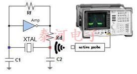
2.驱动电平的测量驱动电平等于工作晶体消耗的功率。 如下图所示,使用电流探头测量流入晶体的电流(Ix)。
功率(驱动电平)的计算公式:DL(功率)=(Ix)2×Re; 其中Ix:有效电流值(rms),Re:有效电阻,Re = R1 x(1 + C0 / CL)2,R1:串联电阻
3.负电阻的测量负电阻用于确定振荡电路的振荡裕度并预测振荡的稳定性。 如下图所示,将可变电阻(VR)与晶体串联,然后逐渐增加电阻。 晶体将以某个值停止振荡。
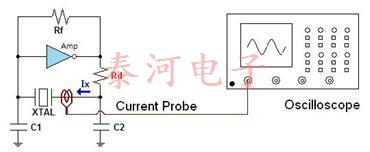
负阻(-R)的计算公式:| -R | = VR + Re,Re = R1 x(1 + C0 / CL)2,R1:串联电阻
- 阅读(307)
- [技术支持]高精度1612小尺寸晶体2019年08月23日 08:47
开发的1.6×1.2 mm GT-Cut石英晶体单元满足低功率,高精度,紧凑和薄型单元在低MHz频率下工作的电流需求。
日本,2014年1月31日:RIVER ELETEC(总部位于日本山梨县的Nirasaki)开发出一种超紧凑,低频率的MHz石英晶体单元。它以更小的封装(不超过1.6×1.2×0.33 mm)提供GT切割石英晶体的出色频率 - 温度特性,适用于频率范围为8至20 MHz的应用。开发利用了我们对10 MHz范围GT切割元件的持续研究以及精密光刻技术的使用年限。
GT-cut石英晶体单元最初是在20世纪40年代开发的,具有出色的频率 - 温度特性,在空白制造方面面临挑战,限制了批量生产。另一方面,对于AT切割石英晶体单元,近年来已经转向支持更高频率以响应更小封装的趋势,从而需要在较低MHz频率下工作的较小的低功率单元。
GT切割石英晶体单元的优点
1.紧凑,薄型单元,工作频率较低
GT切割石英晶体单元的宽度延伸模式(图1)允许封装设计不受毛坯尺寸的限制,从而可以在较低的MHz频率下工作,显着更小,更薄的单元,传统AT切割难以实现的特性石英晶体单元。 (参见表1.)GT切割石英晶体单元的等效电路常数与AT切割单元的等效电路常数相当。
表1:石英晶体单元封装的比较

图1:结合主要(宽度 - 延伸)和次要(长度 - 延伸)振动的模式

比较:GT-Cut石英晶体单元(左)和AT-Cut石英晶体单元(右)
2.在宽温度范围内稳定的频率
GT切割石英晶体单元具有非常优越的频率 - 温度特性(图2)。 该开发产生的单位在-20至+ 70°C范围内具有±3 ppm的显着值,在-40至+ 85°C范围内具有±5ppm的性能,而AT切割石英晶体单元则无法实现这一性能。
3.可以低功率驱动
由于智能手机,平板电脑和可穿戴电子产品采用电池供电,因此低功耗是电子元件的基本特征。鉴于使用AT切割石英晶体单元难以实现稳定的低功率振动,这些元件通常以10μW或更高的速度驱动。相比之下,GT切割石英晶体单元允许设计具有最佳轮廓,尺寸和厚度的振荡器,以最小化振动损失并确保稳定的振荡,即使在5μW或更低的驱动下也是如此。
电池供电的移动设备通常设计为间歇运行,以帮助最大限度地降低功耗。这种装置需要能够快速恢复振荡的晶体。与传统的紧凑型AT切割石英晶体单元相比,GT切割单元的启动振荡时间约为550μs的两倍(与同一振荡电路中的12 MHz FCX-05晶振相同且频率相同)。
GT切割石英晶体单元融合了其他领域的丰富技术专长。
1.轮廓模式振动的设计专业知识
RIVER ELETEC拥有开发利用轮廓模式振动的产品的历史,包括Lame模式共振器。我们为各种振动模式积累了大量的技术和设计专业知识,GT切割石英晶体单元充分利用了这些知识。这些单元在宽度延伸模式下使用轮廓模式振动。
2.高精度光刻
GT切割石英晶体采用数微米(μm)的精密制造生产,采用通过生产音叉石英晶体单元而精制的精密光刻技术。
3.电子束密封,具有极高的可靠性
GT切割晶体采用专有的电子束密封技术,通过金属盖密封在陶瓷封装上进行空气密封。这种保护性密封通过在封装内保持高真空条件来确保高芯性能,并确保其他RIVER CRYSTAL产品具有同样出色的可靠性。
时间表

样品出货计划于2014年2月开始。将这些产品作为频率振荡源提供给许多需要使用AT切割石英晶体单元难以实现的电子设备 - 即在更宽的温度范围内保持稳定的频率,超紧凑,低配置单元工作在较低的MHz频率和低功耗 - 我们继续在各种频率范围内扩展我们的产品线。
- 阅读(239)
- [行业新闻]关于石英晶体的驱动电平2019年08月16日 10:57
驱动电平是振荡期间提供给晶体单元的功率,并使用下面的公式计算。
DL(μW)= R L(Ω)x i 2(mA)
DL:驱动电平
RL:负载下石英晶体谐振器的等效电阻
i:流经晶体谐振器的电流值(有效值)
每个晶体单元都有一个驱动电平标准,并保证驱动电平的上限。关于超过上限的问题是由于与寄生模式的耦合引起的异常振荡(对振荡频率的影响)。以下解释了这个问题。
AT切割晶体单元使用厚度剪切模式作为主振荡模式,但还有许多其他寄生模式(弯曲振动,平面滑动振动等)。图1显示了AT切割晶体单元的振动模式。
这些寄生模式的频率可以与特定温度下主振动的振荡模式的频率组合,从而影响振荡频率。
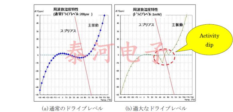
当驱动电平对于规范来说太高时,杂散和主振动可能会耦合。图2显示了当驱动电平正常(驱动电平在标准范围内)和驱动电平过高(驱动电平超出标准范围)时,振荡器频率温度特性如何不同。
当驱动电平正常时,如图2(a)所示绘制平滑的三次曲线。但是,当驱动电平过大时,振荡频率在特定的温度范围内突然变化,如图2(b)所示。现象(称为活动倾向)更有可能出现。
在电路研究中,我们提出了在驱动电平规范范围内的电路常数,以防止活动下降。
- 阅读(440)
- [技术支持]在烤箱控制晶体振荡器中的老化与回收2019年06月24日 15:16
石英晶体振荡器广泛用作各种电子系统中的频率和时间标准。虽然石英晶体振荡器非常适合于任务,但在要求苛刻的应用中的最佳性能,如同任何精密器件一样,需要深入了解器件特质。
衰老是振荡器的长期频率漂移。虽然精心设计和制造可以最大限度地减少运输时的老化,但振荡器的使用寿命会持续老化,并受到断电存储的环境和持续时间的影响。本文重点介绍了造成老化的物理过程,并解释了为何在进行断电存储后,在振荡器频率调整之前强烈建议重新稳定时间。
老龄化有两个基本原因。首先,石英晶体谐振器的频率受电极质量的强烈影响。电极或石英毛坯表面的污染增加了谐振器质量,从而降低了谐振频率。水蒸气是这种污染的罪魁祸首,尽管氧气和碳氢化合物也会引起问题。用于将谐振器安装在其外壳中的导电粘合剂的除气也是一个因素。结晶石英和金属电极都是亚微观尺度的多孔,有大量的小空腔,含有污染物。污染始终存在于某种程度,但生产过程如臭氧清洗,高温真空烘烤,以及使用硬真空可以将污染影响降至几乎可以忽略的程度。
如果污染物保留在原位,污染就不会成为问题。不幸的是,新晶体上的污染,特别是安装在高温下操作的恒温晶体振荡器中的晶体,在蒸发,吸附,冷凝和机械加速的影响下移动。结果,新的振荡器迅速老化,直到污染物运动稳定。
机械应力是振荡器老化的第二个原因。晶体是原子的有序晶格,其形状与原子间距一起决定了晶体的物理性质,如介电常数和弹性。许多这些特性影响共振频率。机械应力使原子晶格变形,稍微改变原子间距,从而稍微改变晶体的物理性质。如果受到应力的晶格恰好是石英晶体谐振器,则结果是谐振频率略有变化。因此,AT切割谐振器暴露于机械应力移位频率。双旋转晶体(例如IT切割或SC切割)部分地受到应力补偿,并且受到应力的影响较小。因此,双重旋转切割的再稳定时间较短,但这些谐振器制造起来要困难得多,并且比普通的AT切割谐振器更昂贵。
石英晶体谐振器中的应力有很多来源;来自安装夹的弹簧作用的安装应力,导电粘合剂在设定时的收缩,来自制造期间的切割和研磨操作的残余应力以及差异的热膨胀和收缩。最后一个因素在烘箱振荡器中特别有意义,因为每次施加功率时晶体从室温加热到约80℃,并且因为晶体石英中的热膨胀系数在每个轴上是不同的。
由于石英传导热量很差,热梯度很陡并且消散得很慢。当谐振器的边缘与安装夹接触时,过热的AT切割谐振器在预热期间会受到强烈的应力引起的频率瞬变。比中心。这个瞬态在图中可见,因为在开启后4到5分钟出现了尖锐的频率下冲。刚刚开启后新振荡器中的残余应力达到最大值,在操作的前几天缓慢放松,直到达到平衡条件。
对于新的振荡器,来自污染物再分配和应力松弛的频率变化高达每天十亿分之几。 VECTRON晶振的标准做法是燃烧或老化新的振荡器,同时持续监测频率,直到日常老化速率稳定。所需的时间取决于振荡器频率和晶体切割以及指定的老化速率。典型的老化持续时间从不到一周到几周不等。
当一个新的“老化”振荡器关闭时会发生什么?当冷却时,静电振荡器重新获得机械应力,应力的大小是炉温和环境温度之差的函数。尽管在较低温度下应力松弛率大大降低,但这种应力最终会消失。
当振荡器关闭时,污染物开始再次向新的平衡状态移动。如前所述,在较低温度下重新分配的速度要小得多。如果断电时间很短,并且存储温度适中,则振荡器将恢复到接近于在短暂预热期后在装运时测量的老化速率。实际频率接近 - 但不相同 - 由于滞后并且因为在断电期间老化持续,但不一定是相同的速率。
延长的断电间隔,或(根据对受试者的一些参考)在断电间隔期间暴露于极端温度允许更大程度的应力松弛和污染物重新分布。在这种情况下,在原始生产老化期间获得的一些老化稳定性丢失。因此,当重新施加功率时,需要更长的再稳定时间来达到先前的老化速率。重建期间有所不同。 24小时后对三次泛音AT切割恒温振荡器的再稳定化表示非应力补偿晶体的非常好的性能。甚至少量晶体污染的存在将显着延长再稳定期。
这在实践中意味着什么?首先,如果可能的话,应该持续为恒温振荡器供电。如果电源中断是不可避免的,请注意振荡器将比正常预热需要一些时间才能恢复到先前的老化速率,并且由于老化和滞后,不太可能返回到完全相同的频率。 AT切割谐振器的迟滞不太可能比10-8中的几个部分好得多。重新稳定期间的频率调整不是一个好主意。凭借其设计精密恒温振荡器的丰富经验,Vectron晶振能够协助确定适当的再稳定期,特别是在断电期超过几天且需要更长的再稳定期的情况下。
- 阅读(287)
- [行业新闻]MtronPTI公司的发源史2019年05月27日 11:24
凭借1965年雷达用精密晶体滤波器的基础,Mtronpti设计和制造了用于高可靠性和恶劣环境应用中的数据定时和射频频谱控制的射频和微波解决方案。Mtronpti成立于2004年,由M-tron Industries,Inc.收购Piezo Technology,Inc.,是LGL Group,Inc.的全资子公司。
在航空航天和国防市场,Mtronpti的数字调谐滤波器支持在存在电磁干扰的情况下进行安全通信。低漂移、高精度振荡器为地面、车辆、空中和卫星通信以及电子对抗提供可靠的频率锁定。抗振动和冲击的水晶钟使雷达图像更加清晰,并有助于监控商用飞机发动机的性能。
对于互联网通信,mtronpti晶振公司具有非常低的噪声和包同步时钟有助于增加带宽,防止蜂窝基站、micro和femto蜂窝以及Wi-Fi接入点的数据丢失。毫米波滤波器确保公司和电信的点对点链接保持无误。
在实验室工作台或消费电子产品生产测试台上,mtronpti超低噪声频率基准振荡器确保了准确的测量。当公共安全至关重要时,mtronpti宽温度范围/防水腔过滤器确保可靠的无线电通信。
卫星链路、相控阵雷达和抗IED干扰机使用mtronpti射频功率放大器将信号增强到天线。
Mtronpti晶振公司位于佛罗里达州奥兰多,在美国和印度制造业,在垂直方向上与基础材料科学、设计和制造方面的丰富经验相结合。凭借AS9100 C版和ISO 9001:2008全球认证、销售和支持,作为公认的服务领导者,MTronpti通过分销合作伙伴支持思科、雷神、爱立信、哈里斯、罗克韦尔柯林斯、联合技术航空和近2000家小型客户等主要原始设备制造商的创新和可靠性
LGL集团公司的工程和设计起源可以追溯到上个世纪初。 1917年,LGL的前身林奇玻璃机械公司成立,并在二十年代末成为玻璃成型机械的成功制造商。该公司后来更名为林奇公司,并于1928年根据印第安纳州法律注册成立。 1946年,林奇被列入“纽约路边交易所”,这是纽约证券交易所MKT的前身。该公司在精密工程,制造和服务领域拥有和经营各种业务的历史悠久。
LGL集团公司(以下简称“公司”)于2007年根据特拉华州法律重新注册,并作为控股公司,其子公司从事定制设计,高度工程化的电子元件制造。该公司的办公室位于佛罗里达州奥兰多市沙德路2525号,邮编32804。公司的普通股在纽约证券交易所股票代码:MKT上以股票代码“LGL”进行交易。
公司通过其主要子公司M-tron Industries,Inc.运营,包括M-tron Industries,Ltd.(“MTRON”)的运营,以及MTRON的子公司Piezo Technology,Inc.和Piezo Technology India Private Ltd.(合称“PTI”)。2004年10月,MTRON和PTI合并为一家公司,拥有业内最广泛的产品组合之一。MTRONPIT和PTI的联合业务被称为“MTRONPIT”。MTRONPIT在奥兰多、佛罗里达、扬克顿、南达科他州和印度诺伊达都有业务。此外,MtronPTI在香港和中国的上海设有销售办事处。
Mtron Industries,Inc.(“MTRON”)始建于1965年,原名为Mechtronics,Industries,Inc.。此后不久,该公司正式更名为M-tron Industries,Inc.。早期,MTRON的主要业务是为CB无线电市场制造晶振。当20世纪70年代末技术发生变化时,MTRON也发生了变化。营销方式的改变和产品的持续发展为公司提供了新的生活。MTRON被称为高质量、高可靠性晶体、振荡器的供应商,在某种程度上,VCXO(压电控制晶振)和TCXO(温度补偿晶振)产品将用于诸如电信基础设施(用于制造电话系统)以及后来的互联网功能等应用。1976年,M-tron Industries,Inc.被收购。2002年,MTRON收购了伊利诺伊州富兰克林公园的Champion Technologies,Inc.的资产。在20世纪80年代中期,Champion是摩托罗拉的子公司。这次收购通过扩大产品供应和客户群,帮助MTRON从2001年和2002年的电信市场崩溃中更快地复苏。
1965年,几乎在MTRON成立的同时,成立了另一家公司,名为Piezo Technology,Inc.。PTI的成立是为了设计和建造用于所有类型设备的晶体滤波器,其中某些类型的噪声需要从电路中过滤出来。多年来,PTI在业务和产品方面都有所发展,包括LC(集总元件)滤波器、TCXO和OCXO(恒温晶体振荡器)产品。PTI的主要市场是军事、航空电子和仪器仪表。1995年,PTI在印度开设了生产基地,2004年M-tron Industries,Inc.收购了Piezo Technology,Inc.。
LGL的业务发展战略主要集中在通过MTRONPTI晶振通过有机增长、扩展到新的地理市场细分市场以及通过其他战略机会扩展现有业务。MtronPTI目前在全球范围内占有一席之地,为大多数需要精确定时和过滤产品的主要市场提供服务。公司的目标细分市场包括高端电信、军事、仪器、空间和航空电子设备(简称“MISA”)。
- 阅读(519)
- [技术支持]石英晶振系列解决方案2019年04月29日 15:17
从早期的无线电到雷达,以及现在的数字计算,每个电路都需要一个时钟或心跳来指导其功能。时序控制从低功率到高精度的各种应用中的处理速率,数据连接和RF传输频带。时间已成为一个多元化的工程领域。考虑到可以设计时钟电路的多种方式以及每年引入该行业的许多进步,工程师应该定期重新考虑其时序考虑因素。以下是基本计时设备列表以及使用它们的最佳时间。
1.LC谐振器
LC谐振器是最简单和常用的定时电路,由放大器,电感器和电容器组成。主要优点包括低成本和易于集成,特别是在高频率下。然而,它不是非常准确,并且随温度变化很大。这种可变性提供了一个额外的属性:宽拉范围。因此,在开发小型或高度集成的压控振荡器(VCO)时,LC是首选的谐振器。这些振荡器在PCB或片上设计用于跟踪或锁定其他频率。由于温度可以使频率+/- 10,000 ppm或更高,因此LC不够精确,无法单独运行。
2.陶瓷谐振器
陶瓷谐振器的主要优点是成本。如果您正在寻找最低成本和稳定的解决方案,那么这项技术可以帮助您实现这一目标。不要指望在整个温度范围内稳定性小于+/- 1000ppm。该谐振器成本低,但不能用于精确或甚至部分精确的定时。玩具,低端设备和低端MCU应用程序等通用应用程序可以摆脱这种不精确的程度。如果您需要更高的精度,其他谐振器将帮助您。
3.石英晶体
石英晶体因其自补偿温度稳定性,出色的初始精度和适中的成本而成为时间之王。作为谐振器,它具有高Q值,可实现极低的在线噪声。批量生产已经对这些设备的精度和成本进行了微调,因此价格适中的晶体现在可以实现+/- 20ppm至+/- 50ppm的总体精度。它具有出色的稳定性,是当今许多连接协议的理想时间基础,从Wi-Fi,Zigbee和蓝牙到汽车LIN / CAN,以太网,UART和工业应用。定时MCU和使用石英晶体的处理器提供的精度可以满足常见的连接协议。但是,有些协议需要更高的性能。晶体的精度可以提高。
4.石英晶体振荡器(XO)
石英晶体振荡器集成了振荡器芯片和石英晶体。它提供了石英的准确性和低噪声优势,但降低了电路板走线引起的可变性。在某些情况下,振荡器芯片还将基本石英频率乘以应用所需的频率。在非常低噪声的系统中使用XO而不是裸石英晶体是必要的,例如高速通信,光学互连,光学模块,测试和测量以及先进的RF应用。XO以高频率提供低噪声,这对于使用普通晶体来说是难以实现的。高性能系统中使用的顶级频率如100MHz,156.25MHz或312.5MHz需要使用XO提供的差分LVPECL,LVDS,HCSL或CML信号进行调理。
5.温度补偿晶振(TCXO)
虽然XO提供缓冲和频率转换,但它们跟踪石英晶体毛坯的精度。若干通信和电信应用,例如点对点RF,GNSS / GPS,移动电话,LPWAN网关和其他精密RF连接系统,需要在整个温度范围内具有+/- 0.5ppm至+/- 2.5ppm的频率稳定性。Stratum III需要+/- 0.28ppm的稳定性。裸露的石英不够稳定,不易达到低于10ppm的稳定性。TCXO经历了一个制造流程,可以测量和校准其频率偏差。明显的缺点是成本。请记住,没有什么比终端系统中不可操作的数据链路更昂贵。
6.烤箱控制的晶体振荡器(OCXO)
OCXO可以达到几乎不可想象的精度水平+/- 0.1ppm至0.1ppb或更高的温度。TCXO技术不仅使用温度校准。OCXO通过添加二阶控制 - 石英毛坯的温度来实现稳定性。在启动时,OCXO将石英毛坯加热到比环境温度高约10度,并将温度控制在该水平,从而最大限度地减少温度扰动。在许多情况下,OCXO还具有机械防护冲击和振动功能,使终端系统能够实现最大时钟精度以满足要求。与军用和雷达相关的许多应用以及用于移动电话的基站收发信台(BTS)需要这种精确度。快速移动车辆中的先进高精度GPS也需要高精度。
7.微电子机械系统(MEMS)
MEMS技术与石英并行发展。MEMS基于硅而非石英晶体,具有小型化和抗冲击和振动的优点。由于与MEMS谐振器相关的复杂性,MEMS的主要缺点是成本。虽然它可以用于晶体,XO和TCXO涵盖的各种应用中,但是当需要高耐久性时,MEMS是最佳的。此外,在尺寸为1.6 x 1.2mm的超小尺寸下,MEMS与晶体竞争非常激烈。可穿戴设备,无线充电板,工业控制,机器人,无人机和AR / VR等应用可以充分利用MEMS的耐用性和尺寸。
- 阅读(221)
- [行业新闻]村田新产品MEMS谐振器应用指南2019年04月20日 09:04
日本村田新研发出一款MEMS谐振器,尺寸仅有0.9*0.6*0.3mm。实现了现石英晶体谐振器达不到超小尺寸,并且低ESR特性的产品。MEMS谐振器的诞生可代替许多石英晶体谐振器。有很多人就想问了什么是MEMS谐振器?它跟振荡器有什么区别?MEMS谐振器有哪些特点?工作原理有哪些?使用都需要注意一些什么问题?等等一大串的问题就随之而来了。
那么我们将一一把问题给大家回复。
首先,大家肯定是会对日本村田陶瓷晶振制作所研发出的产品有些疑问,什么是MEMS呢?其实MEMS指的是微机电系统(Micro Mlectro Mechanical Systems),这种装置运用了半导体生产工艺技术,具有三维微细结构。除了面对MEMS谐振器还有一种是振荡器,MEMS振荡器跟其它普通石英晶体振荡器是一样的,将振荡用电路也谐振器融为一体的装置。可用科尔皮兹振荡电路之类的普通振荡电路驱动。
WMRAG32K76CS1C00R0谐振器是村田MEMS技术的代表作品。该产品具有体极柢的ESR特性以及极小尺寸封装,这个是目前石英晶体谐振器无法实现的突破。极小的尺寸有助于减小安装面积,通过优化IC增益,实现了低ESR的MEMS谐振器,降低了功耗。也可用于回流焊接,引线键合和传递模型。WMRAG32K76CS1C00R0谐振器具有晶体该有的特性,32.768KHZ标频以及20PPM标准稳定偏差。可在-30~+85度下正常工作。驱动电平在0.2μW以内。当您考虑置换晶体的时候,要注意晶体谐振器和MEMS谐振器的负载电容量值不同。
并且要知道MEMS谐振器与普通石英晶体谐振器的区别。
- 阅读(255)
- [技术支持]What is frequency at load capacitance?2019年04月16日 10:07
1. Introduction
When ordering crystals for oscillators that are to operate at a frequency f, e.g. 32.768 kHz or 20 MHz, it is usually not sufficient to specify the frequency of operation alone. While the crystals will oscillate at a frequency near their series resonant frequency, the actual frequency of oscillation is usually slightly different from this frequency (being slightly higher in “parallel resonant circuits”).1
So, suppose you have a crystal oscillator circuit and you want to purchase crystals such that when placed in this circuit the oscillation frequency is f. What do you need to tell the crystal manufacturer to accomplish this? Do you need to send a schematic of the oscillator design with all the associated details of its design, e.g. choice of capacitors, resistors, active elements, and strays associated with the layout? Fortunately, the answer is no. In addition to the frequency f, all that is needed is a single number, the load capacitance CL .
2. What is CL ?
Suppose your crystal oscillator operates at the desired frequency f. At that frequency, the crystal has complex impedance Z, and for the purposes of frequency of operation, this is the only property of the crystal that matters. Therefore, to make your oscillator operate at the frequency f, you need crystals that have impedance Z at the frequency f. So, at worst, all you need to specify is a single complex number Z = R+jX. In fact, it is even simpler than this.
While in principal one should specify the crystal resistance R at the frequency f, usually the crystal-to- crystal variation in R and the oscillator’s sensitivity to this variation are sufficiently low that a specification of R is not necessary. This is not to say that the crystal resistance has no effect; it does. We shall discuss this further in Section 4.
So, that leaves a single value to specify: The crystal reactance X at f. So, one could specify a crystal having a reactance of 400 ? at 20 MHz. Instead,however, this is normally done by specifying a capacitance C L and equating.
where we have set ω = 2πf. Physically, at this frequency, the impedance of the series combination of the crystal and a capacitance C L has zero phase (equivalently, has zero reactance or is purely resistive). See Figure 1. To see this, consider
where the second step follows by Equation (1) and the fact that the reactance of a capacitance C is -1/( ωC).
Figure 1—This series combination has zero-phase impedance at a frequency where the crystal has load capacitance CL
So, the task of assuring proper oscillation frequency is the task of providing components (crystals in this case) that, at the specified frequency, have the required reactance, which is stated in terms of a capacitance CL by Equation (1).2 For example, instead of specifying crystals having a reactance of 400 ? at 20 MHz, we specify crystals having a load capacitance of 20 pF at 20 MHz, or more normally, we specify that the crystal frequency be 20 MHz at a load capacitance of 20 pF.
In “parallel resonant circuits,” CL is positive, typically being between 5 pF and 40 pF. In this case the crystal operates in that narrow frequency band between the crystal’s series and parallel resonant frequencies (F s and F p , respectively).
While a truly “series resonant circuit” does not have a load capacitance associated with it [or perhaps an infinite value by Equation (1)], most “series resonant circuits” actually operate slightly off of the series resonant frequency and therefore do have a finite load capacitance (that can be positive or negative).However, if this offset is small and specifying a load capacitance is not desired, it can either be ignored or handled by a slight offset in the specified frequency f.
As we shall see in Section 4, both the oscillator and the crystal determine C L . However, the crystal’s role is rather weak in that in the limit of zero resistance,the crystal plays no role at all in determining C L . In this limiting case, it makes sense to refer to C L as the oscillator load capacitance as it is determined entirely by the oscillator. However, when it comes time to order crystals, one specifies crystals having frequency f at a load capacitance C L , i.e. it is a condition on the crystal’s frequency. Because of this,it would be reasonable to refer to C L as the crystal load capacitance. For the sake of argument, we simply avoid the issue and use the term loadcapacitance.
注释:1> When ordering crystals for series resonant operation,instead of specifying a value for C L , be sure to state that the frequency f refers to the series-resonant frequency, F s .
2> This is not to say that all aspects of frequency determination are tied to this single number. For example,other aspects of the crystal and oscillator determine whether the correct mode of oscillation is selected and the system’s frequency stability (short and long term).
3. Defining F L at C L
We now take Equation (1) as our defining relation for what we mean by a crystal having a given frequency at a given load capacitance.
Definition: A crystal has frequency F L at a load capacitance C L when the reactance X of the crystal at frequency F L is given by Equation (1), where now ω = 2πF L .
Recall that, around a given mode, the reactance of a crystal increases from negative values, through zero at series resonance, to large positive values near parallel resonance where it rapidly decreases to large negative values, and then again it increases towards zero. (See Reference [1].) By excluding a region around parallel resonance, we have a single frequency for each value of reactance. In this way,we can associate a frequency F L given a value of C L .So, positive values of C L correspond to a frequency between series and parallel resonance. Large negative values of C L , correspond to a frequency below series resonance while smaller negative values correspond to frequencies above parallel resonance.(See Equation (3) below.)
3.1. The crystal frequency equation So, how much does the frequency of oscillation depend on the load capacitance C L ? We can answer this question by determining how the crystal frequency F L depends on the crystal load capacitance CL . One can show that to a very good approximation that
where C 1 and C 0 are the motional and static capacitances of the crystal, respectively. (See Reference [1] for a derivation and discussion of this relation.) For the purposes of this note, we shall refer to Equation (3) as the crystal frequency equation.
This shows the dependence of a crystal oscillator’s operational frequency on its load capacitance and its dependence on the crystal itself. In particular, the fractional frequency change when changing the load capacitance from C L1 to C L2 is given to good approximation by
3.2. Trim sensitivity
Equation (3) gives the dependence of operating frequency F L on the load capacitance C L . The negative fractional rate of change of the frequency with C L is known as the trim sensitivity, TS. Using Equation (3), this is approximately
From this we see that the crystal is more sensitive to given change in C L at lower values of C L .
4. But what determines C L ?
Consider the simple Pierce oscillator consisting of a crystal, an amplifier, and gate and drain capacitors as shown in Figure 2.
There are at least three stray capacitances that must be considered in trying to calculate the load capacitance of the Pierce oscillator circuit.
1. An added capacitance from the input of the amplifier to ground. Sources for this could be the amplifier itself and trace capacitance to ground. As this capacitance is in parallel with C G , we can simply absorb this into our definition of C G . (That is C G is the capacitance of the capacitor to ground plus any additional capacitance to ground on this side of the amplifier.)
2. An added capacitance from the output of the amplifier to ground. Sources for this could be the amplifier itself and trace capacitance to ground. As this capacitance is in parallel with C D , we can simply absorb this into our definition of C D . (That is C D is the capacitance of the capacitor to ground plus any additional capacitance to ground on this side of the amplifier.)
3. A stray capacitance C s shunting the crystal as shown in Figure 2.
Redefining C G and C D as discussed above, it then follows [2] that one of the conditions for oscillation is
Where
is the impedance of the parallel combination of the crystal and the capacitance C s and R o is the output resistance of the amplifier.
It can be shown that the crystal resistance R as a function of load capacitance C L is given approximately by (provided C L is not too small)
where R 1 is the motional resistance of the crystal [1].It then follows that (provided C L – C s is not too small)
And
With these results, Equation (6) gives the following equation for C L
where R ′ is approximated by Equation (9). Note that the equation for C L is actually a bit more complicated than it might seem at first as R ′ depends upon on C L.It can be seen that C L decreases as R 1 increases, and so by Equation (3), the frequency of operation increases with crystal resistance. So, the load capacitance does have a dependence on the crystal itself. But as we have mentioned previously, the variation in crystal resistance and resulting sensitivity to this variation is usually sufficiently low that the dependence can be ignored. (In this case, a nominal value for crystal resistance is used in calculating C L .)
However, sometimes the resistance effect cannot be ignored. Two crystals tuned so that both have exactly the same frequency at a given load capacitance C L can oscillate at different frequencies in the same oscillator if their resistances differ. This slight difference leads to an increase in the observed system frequency variation above that due to crystal frequency calibration errors and the board-to-board component variation.
Note that in the case of zero crystal resistance (or at least negligible compared to the output resistance Ro of the amplifier), Equation (11) gives
So, in this case, the load capacitance is the stray capacitance shunting the crystal plus the series capacitance of the two capacitances on each side of the crystal to ground.
5. Measuring CL
While in principal one could calculate C L from the circuit design, an easier method is simply to measure C L . This is also more reliable since it does not rely on the oscillator circuit model, takes into account the strays associated the layout (which can be difficult to estimate), and it takes into account the effect of crystal resistance. Here are two methods for measuring C L .
5.1 Method 1
This method requires an impedance analyzer, but does not require knowledge of the crystal parameters and is independent of the crystal model.
1. Get a crystal that is similar to those that will be ordered, i.e. having similar frequency andresistance.
2. Place this crystal in the oscillator and measurethe frequency of operation F L . In placing the crystal into the circuit, be careful not to damage it or do anything to cause undue frequency shifts.(If soldered in place, allow it to cool down to room temperature.) A good technique that avoids soldering is simply to press the crystal onto the board’s solder pads using, for example,the eraser end of a pencil and observe the oscillation frequency. Just be careful that the crystal makes full contact with the board. The system can still oscillate at a somewhat higher frequency without the crystal making full contact with the board.
3. Using an impedance analyzer, measure the reactance X of the crystal at the frequency F L determined in Step 2.
4. Calculate C L using Equation (1) and the measured values for F L ( ω = 2πF L ) and X at F L .
5.2 Method 2
This method is dependent upon the four-parameter crystal model and requires knowledge of these parameters (through your own measurement or as provided by the crystal manufacturer).
1. Get a crystal that is similar to those that will be ordered, i.e. having similar frequency and resistance.
2. Characterize this crystal. In particular measure its series frequency Fs , motional capacitance C1,and static capacitance C0.
3. Place this crystal in the oscillator and measure the frequency of operation F L (as in Method 1,Step 2.)
4. Calculate C L using Equation (3) and the measured values for F L , F s , C 1 , and C 0 .
It is recommended that either procedure be followed with at least 3 crystals. When done properly, this technique often gives values for C L that are consistent to about 0.1 pF. Further confidence in the final results can be found by repeating the procedure for a number of boards to estimate the board-to-board variation of C L .
Note that in the above, F L does not have to be precisely the desired oscillation frequency f. That is, the calculated value for C L is not a strong function of the oscillation frequency since normally only the crystal is strongly frequency dependent. If, for some reason, the oscillator does have strong frequency dependent elements, then using this procedure would be quite difficult.
6. Do I really need to specify a value for CL ?
There are at least three cases where a specification of C L is not necessary:
1. You intend to operate the crystals at their series-resonant frequency.
2. You can tolerate large errors in frequency (on theorder of 0.1% or more).
3. The load capacitance of your circuit is sufficiently near the standard value (see crystal data sheet) that the frequency difference is tolerable. This difference can be calculated with Equation (4).
If your application does not meet one of the three conditions above, you should strongly consider estimating the load capacitance of your oscillator and use this value in specifying your crystals.
- 阅读(232)
- [技术支持]什么是三态函数2019年04月01日 14:24
What is Tri-State Function?
トライステート関数とは

1. In oscillator with Tri-state function, oscillator output can be controlled by the Tri-state pin as follows:
Logic High : Output Enable
Logic Low :Output Disable
トライステート機能付きオシレータでは、次のようにトライステートピンでオシレータ出力を制御できます。
ロジックハイ:出力イネーブル
ロジックロー:出力ディセーブル
2. The Tri-state function would allow output pin to assume high-impedance state, effectively removing the oscillator output from the circuit.トライステート機能により、出力ピンをハイインピーダンス状態にすることができ、回路から発振器の出力を効果的に取り除くことができます。
3. Oscillator circuits can remain on or be turned off while output is disabled in Tri-State.
出力がトライステートでディスエーブルされている間、発振回路はオンのままにするかオフにすることができます。
Oscillator Operating Mode in Tri-state:Oscillator Circuits Off
トライステートの発振器動作モード:発振器回路オフ
•Advantage :Lower standby current
•利点:スタンバイ電流が低い
•Drawback :Longer startup time:( Fundamental mode > 0.2mS),( 3rd Overtone mode > 2mS)
•欠点:起動時間が長くなります:(基本モード> 0.2ミリ秒)、(3倍音モード> 2ミリ秒)
Oscillator Operating Mode in Tri-state:Oscillator Circuits On
トライステートのオシレータ動作モード:オシレータ回路オン
•Advantage:Shorter output enable time(< 0.1mS)
利点:短い出力イネーブル時間(<0.1mS)
•Drawback:Higher standby current
欠点:高いスタンバイ電流
Standby Current Comparison between Different Oscillator Operating Mode
異なる発振器動作モード間の待機電流の比較
Standby Current
Supply Voltage(VDD)
1.8V
2.5V
2.8V
3.3V
5V
Oscillator off
22MHz
0.4uA
0.5uA
1.1uA
1.6uA
4.1uA
44MHz
0.4uA
1.5uA
1.7uA
2.3uA
6.1uA
Oscillator on
22MHz
0.33mA
0.5mA
1.16mA
44MHz
2.1mA
3.4mA
13.5mA
•Only PX/PY series have oscillator on/off option when output is disabled.
出力が無効の場合、PX / PYシリーズのみオシレータのオン/オフオプションがあります。
•All other oscillator series have oscillator turned off in Tri-state.
他のすべての発振器シリーズは、トライステートで発振器がオフになっています。
How to Disable Tri-State Function
トライステート機能を無効にする方法

•If Tri-state function is no needed, the Tri-state pin shall be connected to the Vcc pin or left floating.
トライステート機能が不要な場合は、トライステートピンをVccピンに接続するか、フローティングのままにします。
There is a internal pull- up resistor which would enable output if Tri-state pin is left floating.
トライステートピンをフローティングのままにしておくと、出力をイネーブルする内部プルアップ抵抗があります。
•TAITIEN recommends connecting Tri-State pin to VCC if Tri-state function is not needed.
トライステート機能が不要な場合は、トライステート端子をVCCに接続することをお勧めします。
- 阅读(496)
- [行业新闻]FOX crystal型号表2019年03月12日 09:34
FOX CRYSTAL晶振公司成立于1979年,美国福克斯晶振电子有限公司总部位于美国的佛罗里达州的迈尔斯堡。福克斯电子公司的成立使得该公司成为美国领先的高精度,高可靠性的频率元器件制造供应商。按当时的情况来看,FOX晶振公司还是处于一个小型的家族式石英晶体和振荡器的供应商。
美国FOX晶振公司在过去的32年中持续增长,其中一个重要因素离不开其研发部门。福克斯晶振的工程师开发出了几百种产品,而且这些产品为晶体和振荡器的性能,精度以及可靠性带来了认可的新标准。并可以不断的增长业务的需求,缩短了交付晶体的周期。
FOX CRYSTAL Crystal Company was founded in 1979, and Fox Crystal Electronics Co., Ltd. is headquartered in Fort Myers, Florida, USA. The establishment of Fox Electronics has made the company a leading supplier of high-precision, high-reliability frequency components in the United States. According to the situation at the time, FOX Crystal is still a supplier of small family quartz crystals and oscillators.
The US FOX Crystal Company has continued to grow over the past 32 years, and one of the important factors is inseparable from its R&D department. Engineers at Fox Crystal have developed hundreds of products that bring new standards of acceptance for the performance, accuracy and reliability of crystals and oscillators. And can continue to grow business needs, shortening the cycle of delivering crystals.
- 阅读(302)
- [公司新闻]HOSONIC CRYSTAL选型数据表2019年03月11日 09:05
关于HOSONIC鸿星晶振公司可能挺多人也知道,HOSONIC CRYSTAL鸿星晶振股份有限公司成立于1979年在台湾设立登记成立公司,登记的资本为新台币200万元。公司成立之后便于台湾投入石英晶体研发制造.1994年新增资本3400万元,开始大力研发生产石英晶体振荡器,石英晶振,贴片晶振,压控振荡器的研发生产。
About HOSONIC CRYSTAL Company may know that HOSONIC CRYSTAL was established in 1979 to establish a registered company in Taiwan with a registered capital of NT$2 million. After the establishment of the company, it is convenient for Taiwan to invest in the research and development of quartz crystal. In 1994, the company added 34 million yuan of capital, and began to vigorously research and develop the production and production of quartz crystal oscillator, quartz crystal oscillator, patch crystal oscillator and voltage controlled oscillator.
- 阅读(392)
相关搜索
热点聚焦
- 1时钟振荡器XO57CTECNA12M电信设备专用晶振
- 2汽车音响控制器专用晶振403C35D28M63636
- 3XCO时钟振荡器C04310-32.000-EXT-T-TR支持微控制器应用
- 4ABS07W-32.768KHZ-J-2-T音叉晶体可实现最佳的电路内性能
- 5402F24011CAR非常适合支持各种商业和工业应用
- 6无线模块专用微型ECS-240-8-36-TR晶体
- 7DSX321G晶体谐振器1N226000AA0G汽车电子控制板专用晶振
- 8lora模块低功耗温补晶振ECS-327TXO-33-TR
- 9ECS-250-12-33QZ-ADS-TR适合高冲击和高振动环境的理想选择
- 10ECS-200-20-20BM-TR紧凑型SMD晶体是物联网应用的理想选择
 泰河盛微信号

 在线留言
在线留言 收藏网站
收藏网站 网站地图
网站地图
 手机版
手机版
 全球咨询热线:



 快速通道
快速通道
